
Geometry and loading
- Combined mass of two adults
- Standard gravity
- Baseline rope angle above horizontal, loaded
- Attachment height above finished ground
- Topsoil thickness over the clay
- Footing plan width (square)
- Footing depth, top flush with ground
Geotechnical · sample calcsheet · 8 pages
Two adults in a hammock pull each end post sideways, and each post's small concrete footing has to hold that pull in the clay. Will it? The sheet works out the static actions at each support for a range of rope angles, assesses a supplied, simplified rotational model of the footing before trusting it, solves that model in closed form for the limiting horizontal load, and compares the static demand with the unfactored model resistance for three assumed clay strengths. Geotechnical resistance only: the post, its connection and the concrete are taken as overstrength, and no dynamic or partial factors are adopted.
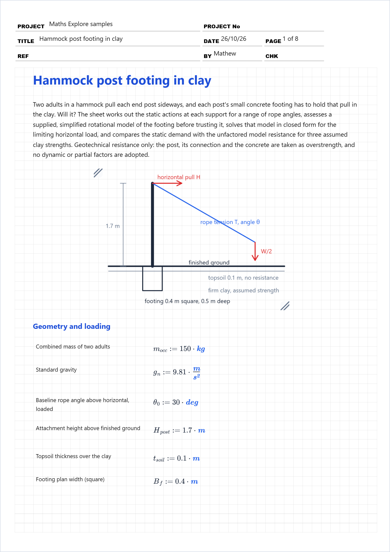
With symmetrical suspension each support carries half the weight vertically. The rope's inclination above horizontal then sets the horizontal pull, V/tan θ, and the rope tension, V/sin θ. The pull acts through the post centreline at the attachment height, so the moment at finished ground level is the pull times that height.
These are static, unfactored actions from the occupants' weight alone. Climbing in, bouncing and swinging add inertia (the tension rises while the occupants accelerate, and swinging shifts load between the two supports), so the peaks exceed the static values. No dynamic amplification or partial factor is adopted here. Those belong to the standard the installation is assessed against, and inventing one would lend the comparison a precision it does not have.
A tighter hammock means a flatter rope. The vertical reaction is fixed by the weight, so the flatter the rope, the harder it pulls: the pull is V/tan θ and the tension V/sin θ, both growing without bound as the angle falls. At 10° each post is pulled sideways with 5.7 times the vertical reaction, against 1.7 times at 30° and exactly the vertical reaction at 45°.
The table reads back exactly by key. Between rows, linear interpolation follows the chord of a convex curve and overstates the pull by about 4 %: use the function for an untabulated angle, and keep interp() for genuinely tabulated data such as a code table.
A hammock loads the footing for seconds to minutes, far less than the time this clay needs to drain, so the clay responds at constant volume and its resistance is governed by the undrained shear strength (the φ = 0 idealisation of Skempton, 1948). That makes a total-stress undrained assessment the appropriate short-term check. It says nothing about the long term: seasonal moisture change, surface softening and fissuring can lower the strength available to a lightly loaded shallow block, and a sustained pull would need a drained assessment.
The supplied model takes the footing as a rigid block rotating in the clay about a reaction-reversal depth below the clay surface: above it the front face mobilises a uniform limiting pressure of twice the undrained strength resisting the pull, below it the back face mobilises the same pressure the other way. Base adhesion, side-face shear and the resisting moment from eccentric bearing are omitted, the block does not pivot about its toe, and full passive pressure is not assumed on one face over the whole embedment.
That mechanism is the free-headed short rigid pile of Broms (1964), and the same force-and-moment balance underlies the embedded-post depth formula of IBC §1807.3. The uniform pressure of twice the strength equals the ground-surface term of the stiff-clay criterion of Reese, Cox and Koop (1975) and sits below Matlock's (1970) three times; both climb to nine to eleven times the strength with depth. Broms, by contrast, gives the top 1.5 widths in clay no resistance at all, which for this 0.4 m embedment would leave none.
So the model is a defensible idealisation for a comparison (low against published pressures at depth, optimistic against Broms at the surface), but omitting resistance components does not make it conservative overall, and it is not a validated design method. A better-supported assessment would treat the block as a short rigid pile with a depth-varying limiting pressure (Brinch Hansen, 1961), including base bearing and side shear, or apply the IBC embedded-post method; both need a measured strength profile, the clay unit weight and an allowable lateral bearing value, none of which is invented here. Every number from the supplied model is an illustrative model result.
The occupants' downward reaction and the footing's own weight press on the clay beneath the base; the resisting moment from that eccentric bearing is excluded from this lateral-only model. For a later alternative method, the vertical load it would bring:
Horizontal balance of the pull F against the front reaction q·a and the back reaction q·(D − a) gives F = q(2a − D). Moments about the clay surface, with the pull at height h above it, the front reaction at depth a/2 and the back reaction at (a + D)/2, give F·h = q(D²/2 − a²). Eliminating a: F(h + D/2) + F²/(4q) = qD²/4, a quadratic in F with the roots solved below without iteration.
Only the horizontal pull enters the lateral assessment: the 1.47 kN rope tension is not the footing demand, its 1.27 kN horizontal component is. Even the 50 kPa case resists only 0.80 kN at the attachment, so the static demand exceeds the unfactored model resistance by a factor of 1.6 to 3.2 across the assumed strengths.