Maths Explore

Geotechnical · worked example · 5 pages

Retaining wall stability

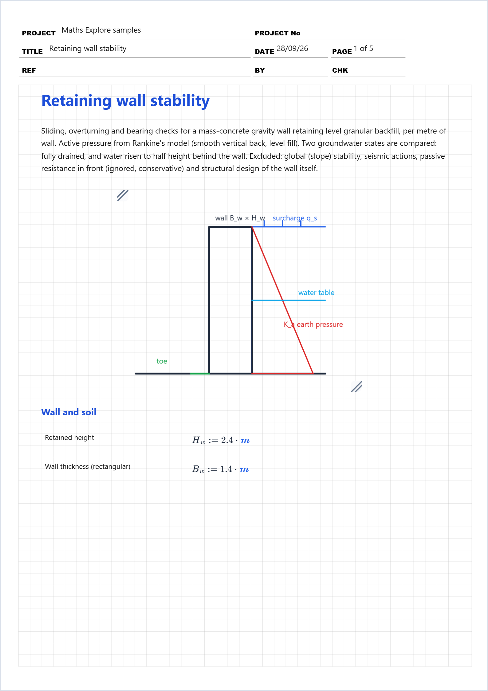
Sliding, overturning and bearing checks for a mass-concrete gravity wall retaining level granular backfill, per metre of wall. Active pressure from Rankine's model (smooth vertical back, level fill). Two groundwater states are compared: fully drained, and water risen to half height behind the wall. Excluded: global (slope) stability, seismic actions, passive resistance in front (ignored, conservative) and structural design of the wall itself.

Open this example in Maths Explore

No account needed. Change any input and every result below it updates.

First page of the Retaining wall stability worked example in Maths Explore
The first page of the calcsheet as it appears in Maths Explore.

What this calculation covers

Wall and soil

  • Retained height
  • Wall thickness (rectangular)
  • Unit weight of concrete
  • Moist unit weight of backfill
  • Saturated unit weight of backfill
  • Unit weight of water
  • Backfill friction angle
  • Surcharge behind the wall
  • Base friction coefficient
  • Allowable bearing pressure

Active pressure and wall weight

  • Rankine active coefficient
  • Wall weight per metre

Dry (fully drained) forces per metre

  • Soil thrust, resultant at H/3
  • Surcharge thrust, at H/2
  • Total horizontal thrust

Dry stability checks

  • Factor of safety against sliding
  • Sliding (target 1.5)
  • Overturning moment about the toe
  • Stabilising moment about the toe
  • Factor of safety against overturning
  • Overturning (target 2.0)

Bearing under the base (dry)

  • Eccentricity of the base reaction
  • Reaction within the middle third
  • Peak bearing pressure at the toe
  • Bearing pressure acceptable

Water at half height

With drainage blocked, water stands to H/2: moist soil above, buoyant soil plus full hydrostatic pressure below. The layered thrusts, each per metre of wall:

  • Depth of moist soil above the water
  • Moist wedge above the water table
  • Weight of moist soil pressing on the wet layer
  • Buoyant soil below the water table
  • Hydrostatic water pressure
  • Total wet thrust

Uplift under the base

The wall is cast directly on the soil with no drainage blanket or shear key, so blocked drainage also pressurises the base: assume uplift varying linearly from the full 1.2 m head at the heel to zero at the toe (the standard USACE assumption). Uplift subtracts from the weight available for base friction.

  • Uplift resultant (triangular)
  • Effective normal force on the base
  • Sliding safety factor, wet
  • Sliding when wet (target 1.5)

Results summary

  • Dry, the 1.4 m wall slides at FS 1.89, overturns at FS 3.03 and bears 115 kPa — all comfortable. Blocked drainage changes the verdict: water at half height raises the thrust from 21.3 to 26.5 kN/m AND lifts 8.2 kN/m off the base, so the wet sliding factor drops to about 1.37 and FAILS the 1.5 target. This wall relies on its drainage; without it, widen the base, add a key, or keep the water out. (Wet overturning and bearing follow the same method with the uplift moments included.)

Try changing…

  • Restore drainage (h_u → 0) — thrust and uplift both vanish and sliding returns to FS 1.89.
  • Widen the base to 1.6 m — wet sliding recovers to about FS 1.56 and every dry factor grows.
  • Drop φ to 25° — K_a jumps from 0.33 to 0.41 and the dry sliding margin nearly vanishes.

All worked examples